Bloggo
A GitHub pages blog
8 bit computer series:
starting up:
I’m not sure when exactly, but at some point last year, I saw a post about Ben Eater’s 8bit computer series on youtube. It’s great, and Ben is a dedicated teacher. I reccomend checking it out if you are interested in learning about how computers work.
(I’m not sure I will be teaching much of anything in this series of posts - but you may find them entertaining if you enjoy photos of electronics, screenshots of code, and sarcasm).
After watching a few of the videos in the series, I immediately decided to order a bunch of ttl stuff from Jameco, and start building. While I waited for ups
to deliver my new goodies, I thought it would be fun to
write a little Typescript simulation of a latch and clock before putting it together on a bread board.
I slowly built up the simulated and hardware versions of an 8bit computer, and a year later of random weekends I have a project I would like to document. Mostly for myself, but I think others may find it interesting for a few moments.
I’m still not done with this project, and will continue to work on it - the rest of this post will be an overview of where I’ve gone so far. In future posts I’ll dive deeper into each of those sections until I’m caught up.
hardware:
Eventually I got some parts in the mail and set about building the circuits for an 8 bit computer. The design is mostly based on Ben Eater’s build - which I believe is based on a combination of the SAP1/2 (simple as possible) computer designs from the book Digital Computer Electronics, by Malvino and Brown. I also took some ideas from Elements Of Computing Systems Another good read.
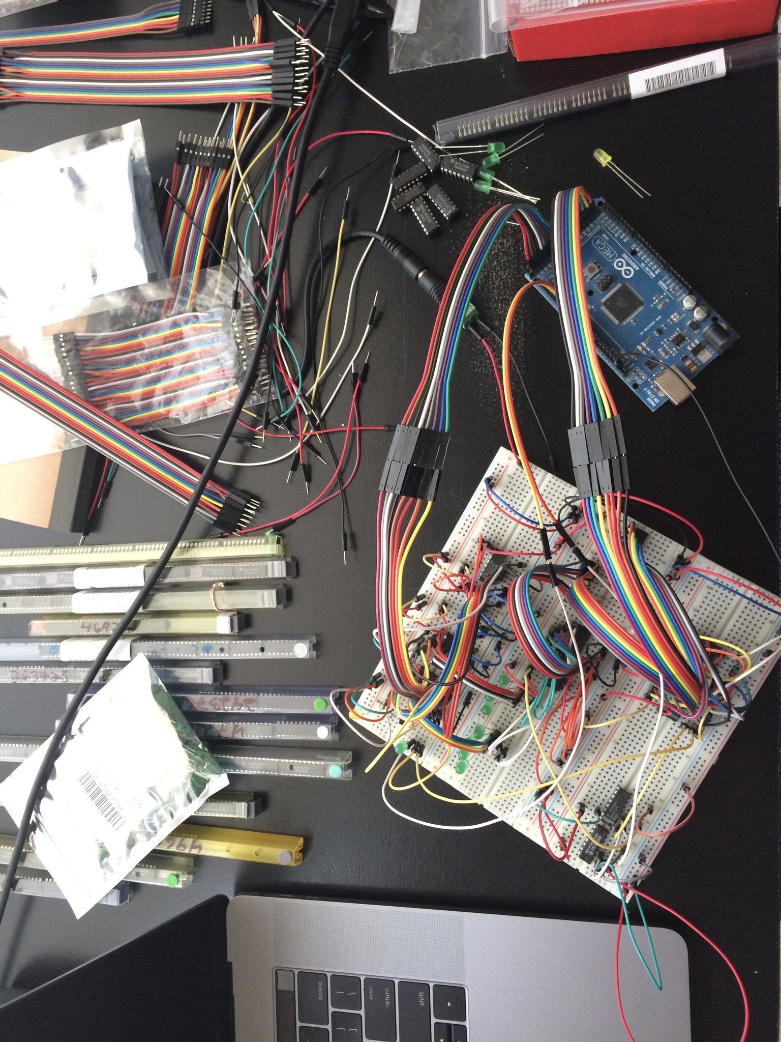
I started building stuff on breadboards until I ran into reliablity problems. At some point, I spent a few hours debugging why I couldn’t write to the SRAM chip in the picture above. Finally I noticed the chip had simply popped a millimeter up out of the breadboard.
At this point I decided to start soldering. It turns out this took a lot longer, smelled worse, and still required me to build things on breadboards first to make sure the design was ready to solder up. I used some solderable breadboards from Adafruit, so transfering from breadboard to protoboard was pretty simple at least.
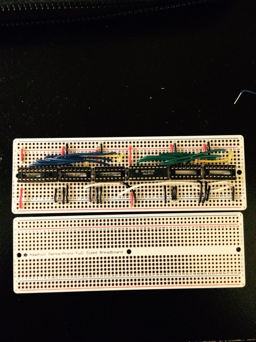
At a certain point I got a bit weary soldering up these boards, invariably finding a mistake during testing of each module, and needing to desolder them and fix them up.
software:
I decided to move back to the simulator for a bit and let the hardware rest.
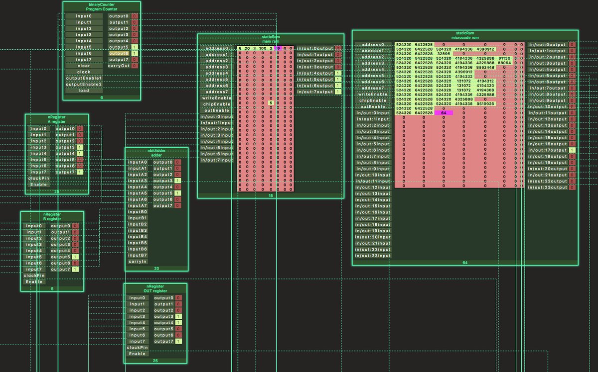
This simulator is written in Typescript. It is capable of representing some basic gates, and logic chips. It is event based, with a simple task scheduler.
The computer it simulates can perform additions, subtractions, and conditional jumps (if statements).
Parts can be instantiated and connected together with Wires. The simulator cannot represent nets or two wires connecting to each
other directly, so a bus or large multiplexer part is used to represent this.
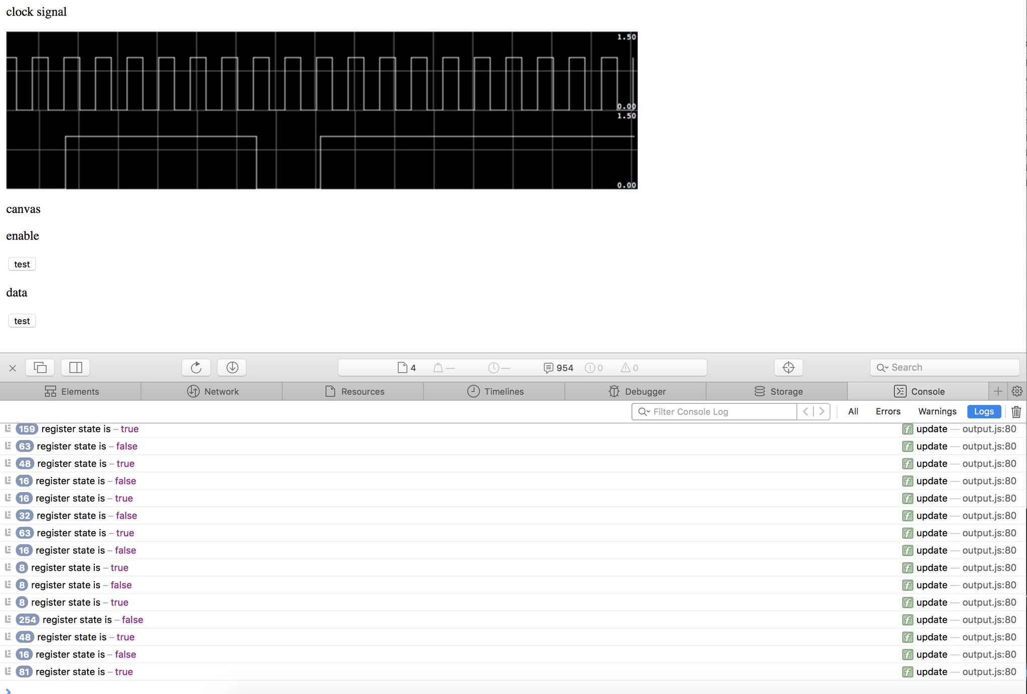
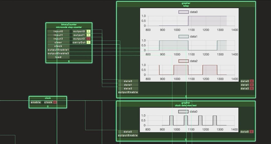
Each part has a view, these views are rendered with React. Below is an example of a view which graphs any input signals.
more software:
One of the more recent experiments I have tried is writing a generator that converts the graph of parts and wires in the simulator into verilog. Verilog is a hardware description language used to configure FPGAs. (field programmable gate arrays). My understanding is that these chips are essentially arrays of memory and gates, which can be rewired using a language like verilog.
There were some bumps along the way, but with some hand tuning after the generation process I am able to convert the simulated computer to verilog and get it running on an FPGA. This is nice because the computer design can be modified in the simulator and new verilog generated based on those changes.
In the next post - I’ll explain the current design of the computers instruction set and where I want to go next.